 Membrane carportsClassic membrane shelters→
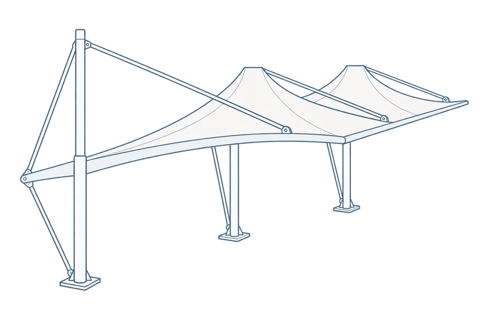 Solar carportsParking meets green energy→
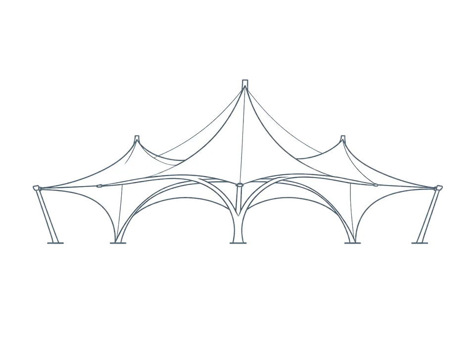 Landscape canopiesParks and leisure spaces→
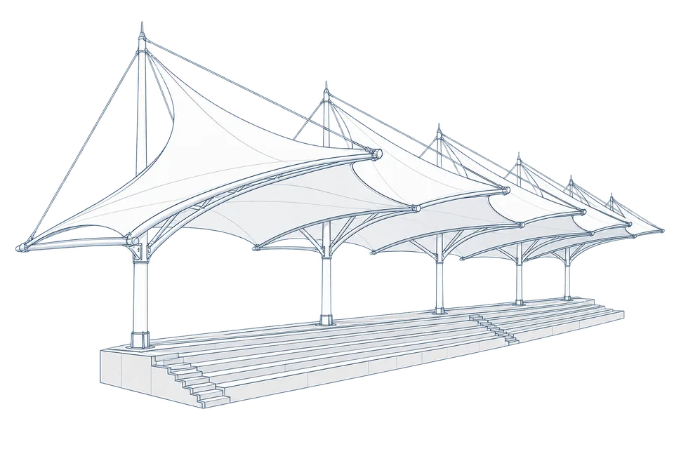 Grandstand canopiesSports venue shelters→
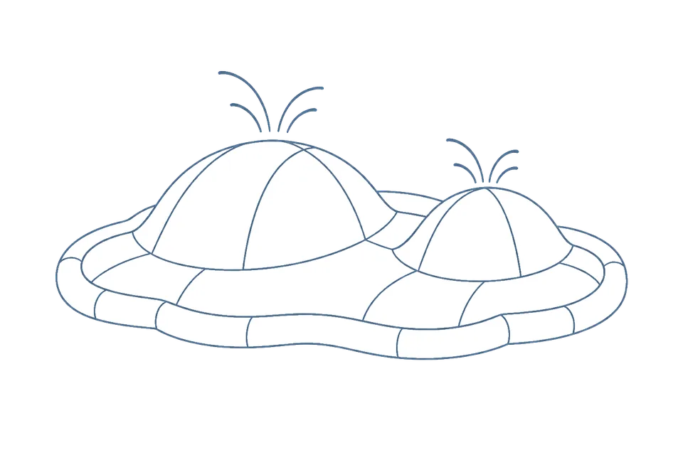 Inflatable play cloudsFamily play areas→
 Wastewater coversEnvironmental infrastructure→
 Fuel station canopiesStation shelters→
 Entrance canopiesWalkways and entrances→
Cutting and joining architectural membranes
Membrane cutting converts a designed curved surface into panels that can be fabricated and joined. Roof projection describes plan coverage, not cutting dimensions. Cutting also considers material orientation, deformation, seams and edge connections.
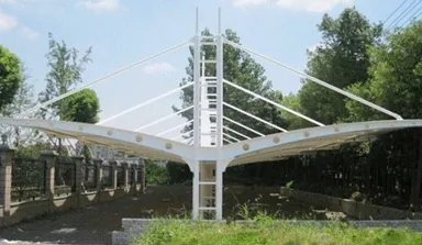
Information needed to move from surface to fabrication drawing
Fabrication drawings should identify panel shapes, numbers, material directions, connection edges and installation positions. Material behaviour and pretension affect cutting analysis. Recheck the design when changing material models rather than keeping old cutting data and changing only the purchase schedule.
Joining does not use one universal adhesive method
Different membranes require different seam and fabrication conditions. Use processes permitted by the product and design. Coordinate seam positions, reinforced edges and corner connections with forces, drainage and installation rather than simply minimising seams or seeking a smooth appearance.
Make site verification straightforward
Retain material-batch and fabrication-check records, label membrane units and packages, and provide orientation information matching installation drawings. Investigate mismatched numbers, sizes or connection positions before proceeding; do not resolve them by forced stretching or arbitrary trimming.
More images